Description
description / manual
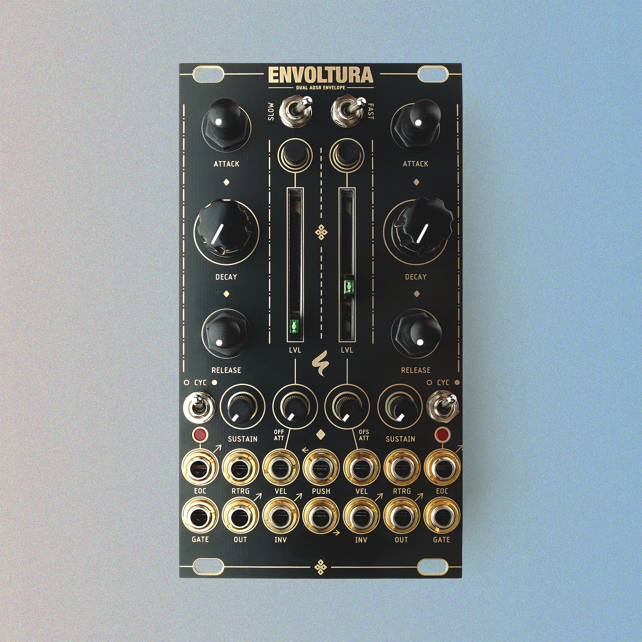
Furthermore, an end-of-cycle GATE signal can be accessed from the EOC socket, which outputs a gate signal when the sustain phase of the envelope ends. The signal remains high until the start of the next attack phase. The gate is indicated by an LED. You have also the flexibility to retrigger the DECAY phase of the envelope by applying a trigger signal to the RTRG input.
IN addition to manual level adjustment via the slider level potentiometer, you can modulate the envelope’s level using an internal VCA by patching a CV signal to the VEL input socket. An exclusive attenuator enables precise control over the level modulation.
For dynamic modulation, simply patch any CV source to the PUSH inputs and manipulate both the envelope’s length and level. Fine-tune the overall length range with the SLOW/FAST switches, and if desired, activate the CYC switch to let the envelopes cycle within specific ranges. Please note that cycling may stop for very fast cycles and that the envelope doesn´t restart from 0 volts.
Finally, you can also trigger each envelope manually. Please note that both ADSRs are normalised to each other, so that pressing a button always triggers both envelopes, unless a patch cable is connected to the gate input of the other.
key features
-
Based on System 100M 140 Module
-
Dual ADSR
-
CV Level Control
-
Inverted Output
-
Retrigger
-
Push Inputs
-
Short and Fast Switch
-
Manual Trigger Buttons
-
Cycle Functionality
-
Skiff friendly
-
Wrong polarity protection
specs & downloads
-
width: 14 HP
-
depth: 30 mm
-
power: 89 mA @ +12V / 56 mA @ -12V
