Description
Probably SINGER is one of the best equipped DIY PT2399 Delays available. It is the consequence of years of development of other delay effects such as DELAY V2 and GRITZNER and now combines new and old functions in one module. Why another PT2399 Delay? Well, because the PT2399 is a very special kind of delay with its own and very unique character we all love and we want CV control over most parameters. In contrast to DELAY V2 and GRITZNER, SINGER was made to explore the boundaries of the PT2399 chip and is able to create all sorts of crazy delay, glitch and noise sounds. It is rather specialized on short delay times, but can create some really nice delay and feedback craziness.
SINGER has two audio inputs IN A and IN B, whereas IN B includes a high pass filter that attenuates frequencies below 320Hz. Especially for effect sends it is helpful to only introduce a high pass filtered delay effect to the mix. You can switch between IN A and IN B by using the A/B switch (switch MAN / LFO set to MAN) or by introducing a CV gate signal to the A/B GATE input jack. When the CV gate signal is high, only IN B will be routed to the delay circuitry indicated by the IN B LED. It is also possible to switch between both inputs using the internal LFO (switch MAN / LFO set to LFO). This way you can create some really unique delay cascades using two different audio signals.
The DELAY TIME can be changed with the large DLY TME knob. The range is set to be too large for the PT2399 chip to handle. Consequently turning the knob from 2 o´clock on clockwise will create crazy glitches and noise artifacts. Cleaner delay times can be achieved by settings from 7 to 12 o´clock. The delay time can be changed via CV at the TIME CV input jack. A dedicated DLY CV attenuator let´s you decrease the amount of CV that is being applied. Additionally an internal LFO can control delay time if nothing is patched into the TIME CV jack and the DLY CV knob is turned to the right.
The LFO rate can be set with the LFO RATE potentiometer and the LFO cycle can be reset by a CV gate or trigger signal that is patched to the LFO RESET input jack. You may choose to use a triangle or square wave LFO with the help of the TRI/SQU switch. The LFO is normalized to delay rate and feedback via the dedicated attenuators if nothing is patched to the corresponding CV input jacks. The LFO rate LED only indicates LFO waves controlling delay rates after attenuation. The LFO is also normalized to the A/B input switch if the MAN / LFO switch is set to LFO.
A DRY/WET potentiometer sets the amount of delay effect that is applied to the OUT jack. On top the level of the wet signal can be changed with the IN attenuator. Hence if the DRY/WET pot is fully clockwise and the IN attenuator is fully counter-clockwise, no signal is audible at the OUT jack.
FEEDBACK may be changed with the help of the FEEDBACK knob and can also be controlled via CV at the FDBK CV jack and the dedicated FDBK CV attenuator. If nothing is patched to the FDBK CV jack you can also route the internal LFO to control the feedback amount if you turn the FDBK CV attenuator to the right.
VCA CV provides the opportunity to control the level of amplification of the wet signal via control voltages such as an envelope or an LFO.
The WET output supplies the pure delay signal at any time.
Details:
• Analog Delay
• CV Control over most Parameters
• Two Inputs
• Internal LFO
• WET Output
• Wrong polarity protection
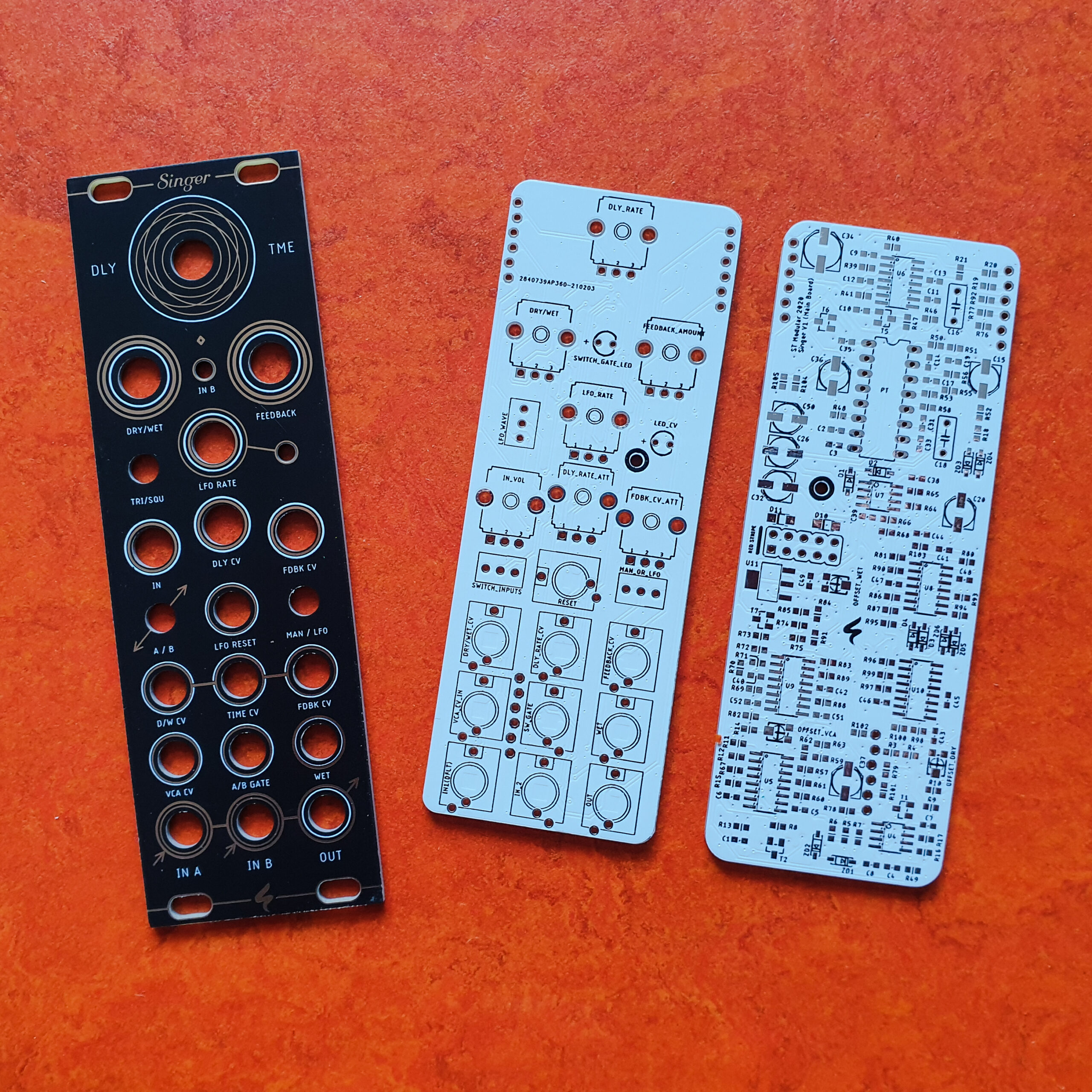
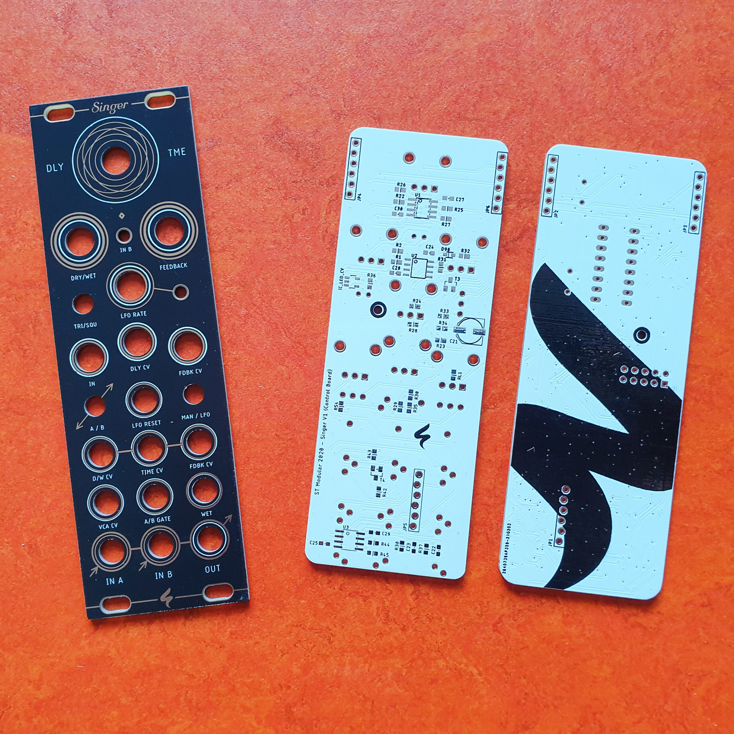
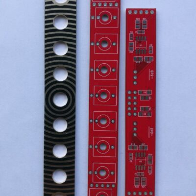
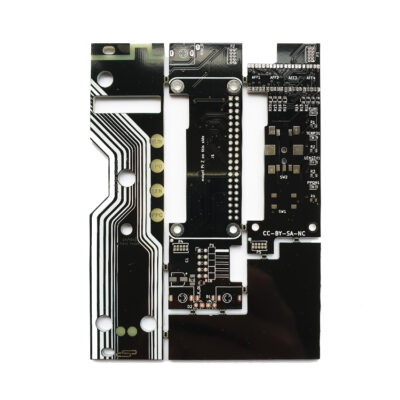
The module consists of three boards:
• Front PCB Panel
• Control PCB
• Main PCB
- 45 mA +12V
- 29 mA -12V
- 0 mA 5V
- 45 mm deep
