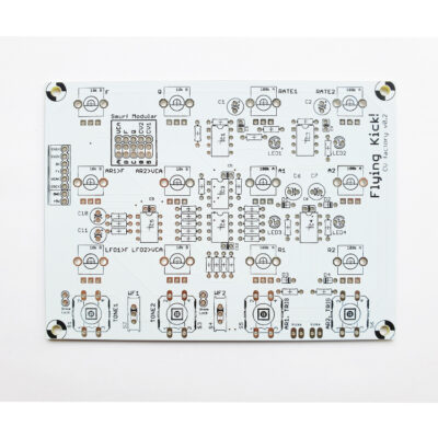
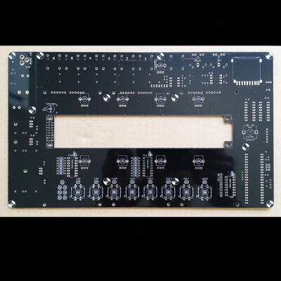
Description
Link for differing resistor values if you use alternate VCA chips
This is a design I did way back in my early years, so you’ll have to bear with the ugly pcb layouts. And sorry, this design is absolutely free from tubes and transformers. But it has a nice moving coil meter at least.
My reason for doing this clone is that the SSL is one of the worlds widely recognized stereo mix compressors – it has a well known sound, and is lusted after by many recording engenieers. But the SSL4000 desk is priced as to be out of reach for most small studio owners. This design is – as you’ll see – quite simple, easy and economically reachable, so I thought it would make a fine DIY-project for people that know their soldering iron and wants to start building pro quality DIY audio equipment. The beauty of this design is that – contrary to a lot of other esoteric projects – the components are (relatively) easy available anywhere, and no special knowledge, tools or adjustments are needed.
The compressor is cloned from our good old SSL4044E desk, dating back from ’85. The SSL mixbus compressor is an integral part of the mixer’s main quad fader and autofade system – cards 82E26 and 82E27, and as you can see if you compare these to my schematic, a series of changes have been made for rehousing the circuit. The main changes concerns the electronically balanced input and output and the removal of unneded components regarding the autofade and main fader circuits. Another change is that the sidechain is common to both VCA’s, making better tracking abilities – your mix wont’ “tilt” so easy when you’re compressing heavily. We did things like that to the SSL in the old days. This might seem like a big change, but actually the sonics are preserved very close to the original, and tracking errors are cancelled.
THE PCB’S:
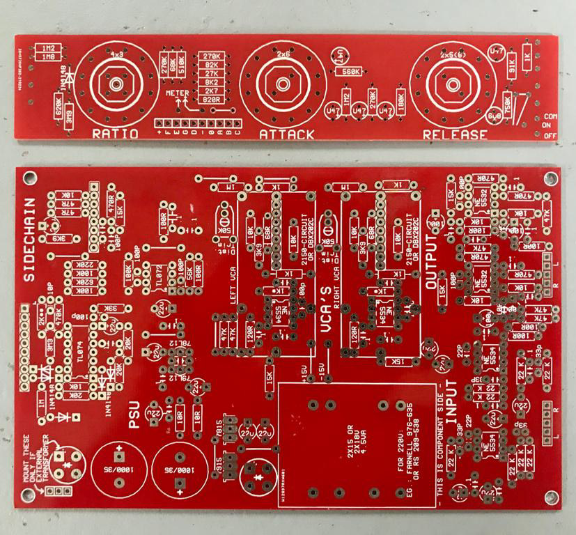
The PCB are in two parts. One is the mainboard, carrying most of the electronic and the power supply. There’s space for a on-board power transformer, but depending on the quality and size of this, you might want to mount a transformer – preferably a toroid type (2x15V, say 10VA or more) – off the pcb. Always take care when handling mains voltages!!. The main board is 100x160mm “eurocard”, a pcb size easy to get as readily photo-sensitized, and also easy to expose evenly. When mounting components onto the PCB, use IC sockets – the “turned pin” types are the best. For the THAT VCA’s (that are single-in-line types) just cut a 16-pin socket in halves.
Observe that one of the three VCA’s (the SC. VCA) is oriented reversed compared to the others, and two NE5534’s are also mounted differently. Also take care that the housings of the 7815/7915 voltage regulators dont touch each other, one carries 0V, the other -15V. No cooling should be needed for the regulators. Note that if you use off-PCB mounted trafo you put in the upper bridge rectifier, and with onboard trafo the lower. Around the output stage the PCB gets a little overcrowded, so be stratetic in the order you mount the components. Sorry about this, but – as said – this is a very early layout, and “if it works – dont fix it”. If you run completely out of room, you could always mount come of the smaller capacitors from the underside of the PCB
The 100nF bypass caps are standard 5mm polyester types – marked “.1″ on the component overlay – and 100pF and downward are all ceramics. The signal carrying 22u and 100u electrolytics are high quality, low ESR types, the PSU decoupling are standards. Mount the PCB in the case using 5-10mm threaded stand-off spacers, and remember to use insulating washers under the PCB to avoid possible ground loops and other trouble.
Fuse the primary of the transformator with about 25 watts worth of fuse, current depending on your local voltage. The easiest way is to use an IEC power inlet with integral fuseholder. For connections between the boards, and to and from the in/outputs, you can use pcb connectors like I did, or just solder the wires directly onto the PCB (there’s not much space to do so – you may want to solder the wires onto the underside of the PCB).
The chassis should be connected to 0V at – and only at – the ground (pin1) of one of the input XLR’s. In case you choose a IEC power inlet connector with a power ground, you should connect it to this point also.
For the power switch I prefer a rotary type, but any type heavy enough to safely carry mains voltages will do.
The second PCB is 30x160mm (one third of a 100×160 piece), connects to the mainboard via a 10 pole cable, and carries the controls – the switches for ratio, attack and release. Here you also attach the makeup gain and threshold pots, the bypass switch, as well as the meter and the occational power-on led.
The size of this PCB is made to fit behind the front of a 19” 1u case, making wireing quite simple. Note that, depending on your 19″1u cabinet, there might not be room for an angled PCB connector. Then instead solder directly to the trackside of the PCB (see pic).
For the switches you need the “Lorlin” type – it’s manufactured by a lot of different companys under different names. The attack and release switches are 2×6-types, the release should be programmed to 2×5 positions, and the bypass and ratio are 4×3-types, the bypass programmed to 4×2. Programming is done by taking off the nut and relocating the washer/locking pin beneath it. The value of the two pots is 50K lin.
The pots dont have to be of any particular quality, as they wont pass audio, just carry dc: Instead focus on getting a good damped feeling – I dont know why, but quality and feel never seems to meet but in esotericly-prized hifi.
The artwork files are in PDF format to maintain scale. Please note that the PCB (copper) side is drawn MIRROR’ED – enabling closer printout-to-photoresist contact when making the PCB. If in doubt, use the text on the board as reference. The easiest way to handle PDF-files on Internet is to right-click on the link and select “save target as”. This is because most browsers don’t allow saving PDF documents.
