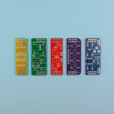
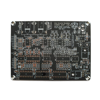
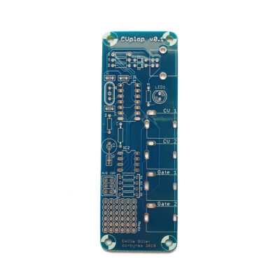
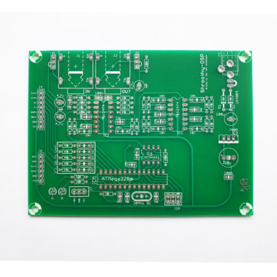
Description
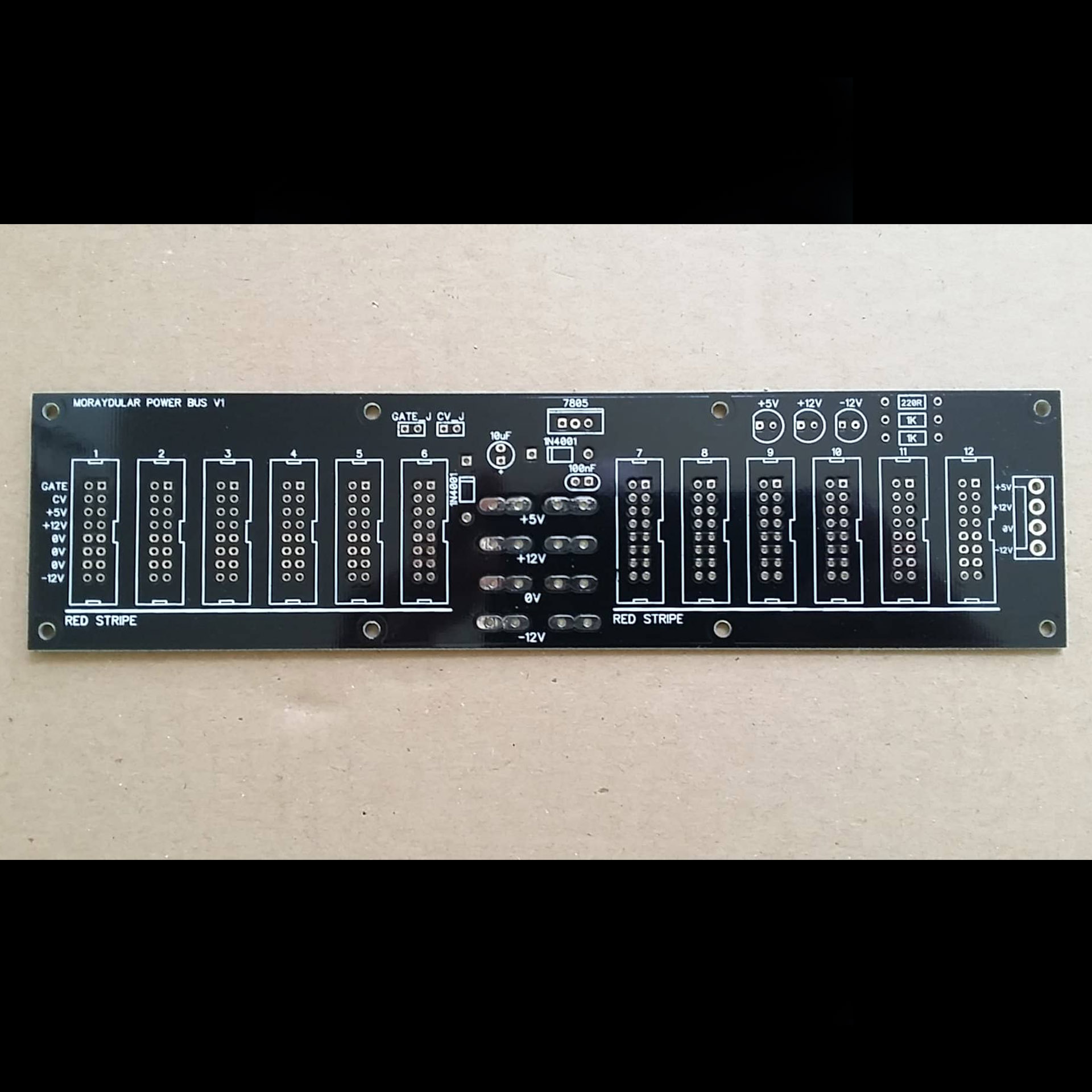
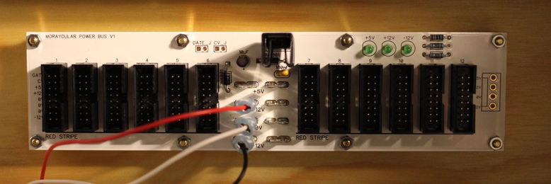
Populating the PCB should be relatively straightforward. Some notes:
- The LED polarity follows standard convention: the short leg / cathode / notched side of LED goes where there’s a notch in the silkscreen.
- The pads for connectors have quite wide thermal reliefs, so soldering them may require some extra heat and patience. In particular, the -12V (bottom row) pins in ribbon connectors will take some warming up for the solder to flow properly.
- When using mounting tabs, you may want to solder them on both sides for extra sturdiness because it usually takes some force to detach the cables.
- If not building the +5V adapter, leave out parts as indicated in BOM below
When using onboard +5V in multiple bus board system, either build the regulator circuit for all boards and leave out +5V link cables or populate the regulator circuit for just one board and distribute +5V to all boards. Never link +5V rails of two boards together if they both already have their own +5V feeds.
Bill of Materials
For plain passive board:
- 12x 16-pin (2×8) 0.1″ shrouded box header (eg. Reichelt WSL 16G) OR unshrouded pin strip
- 6x PCB-mount Faston / Abiko style mounting tabs (eg. Reichelt FS-P 6,35)
- Alternative: 1x 4-pin 0.156″ PCB mount connector (MTA156, Molex KK .156)
- Or you can just solder the wires from PSU directly to the PCB
- 3x 3mm LEDs
- 3x Current limiting resistors according to LEDs you’ve chosen (2x 1K, 1x 220R as indicated on PCB silkscreen should be fine at least for normal red or green leds)
For +5V onboard regulation add the following:
- 1x 7805 voltage regulator
- Use a heatsink according to your planned current draw
- Pin-compatible DC-DCs such as OKI-78SR-5/1.5-W36-C should work and provide more current with better efficiency and no heatsink required, but currently untested
- 2x standard rectifier diodes, any of 1N4001…1N4007 will do
- 1x 10uF electrolytic capacitor, 16V or higher voltage rating
- 1x 100nF ceramic capacitor
