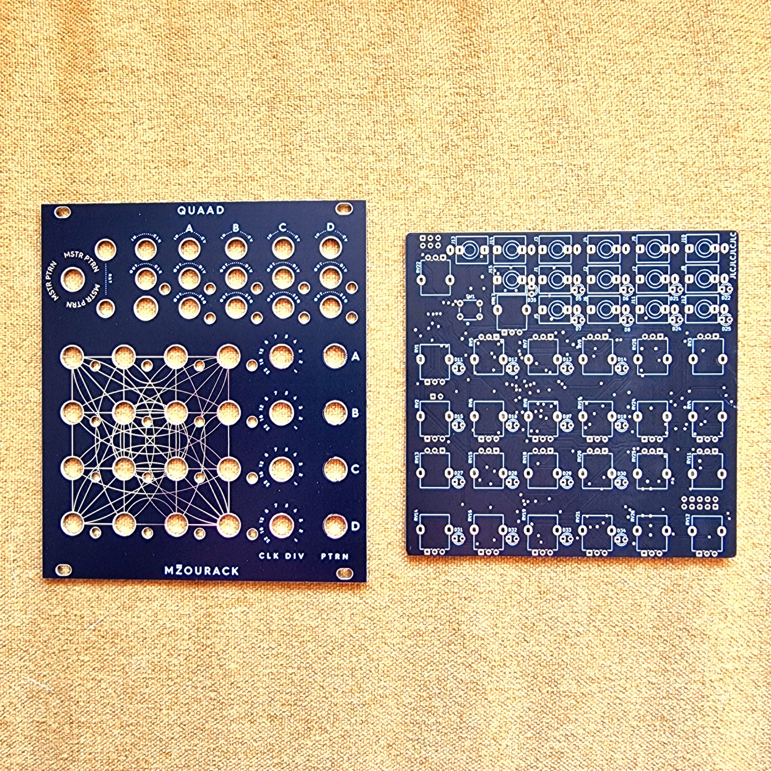
Description
QUAAD
quad 4-step Eurorack CV sequencer
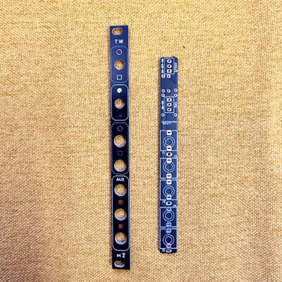
pairs well with MZOURACK – Trigger Warning
current version:
PCB V1.1
Panel V1.1
Features
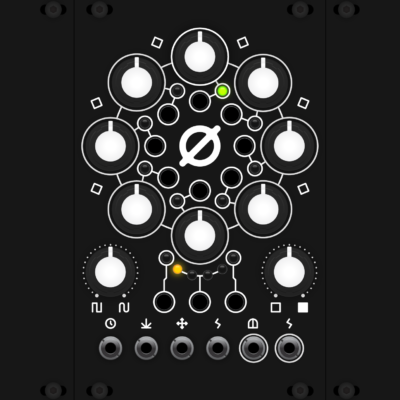
This module is basically 4 independent 4-step sequencers. Each of them features a CV output (0-5V), a clock divider (1-2-3-4-5-7-8-12-16-32 divisions) and a pattern setting. There are 6 patterns available, each one unique, as there are no repeating 4-step sequences between the looped patterns. Patterns can be changed per-sequence via a dedicated knob or via CV, aswell as globally using the MSTR PTRN knob, which basically adds a CV offset to each of the pattern CV inputs. The full range of patterns can be accesed via the pot corresponding to pattern changes of individual sequencers, the MSTR PTRN knob or via 0-5V CV. The patterns are looped, so that when, for example, you are on the last of the 6 patterns and add some positive CV offset, you will go back to the first one and then further on… The patterns are determined by this variable in the Arduino code:
int patterns[] = {1, 2, 3, 4,
                  1, 2, 4, 3,
                  2, 4, 1, 3,
                  3, 4, 2, 1,
                  4, 2, 3, 1,
                  4, 3, 2, 1};
The sequencer can be reset via a gate or manually using a button. With nothing patched into the clock input, the module is clocked internally, the tempo can be set via a potentiometer. The clock output outputs this internal clock when no external clock input is patched in, otherwise, the incoming clock signal is buffered through this output.
The module is 22HP, no 5V source required from the rack.
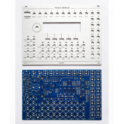
Not much to say here, the build is fairly straight forward. It features SMD components, the passives are 0603.
Firmware
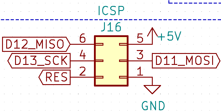
The Atmega328P is running on Arduino code – this means an Arduino bootloader needs to be flashed before the .ino code. To flash it, you can use an arduino (uno or nano for example) and a couple of jumper wires. I recommend to flash the module disconnected from the rack – the 5V needed to run the chip can be provided via the ICSP header. I used a USBASP from aliexpress, it works great but was quite hard to get working, so I cannot recommend it. If you do go down the USBASP route, note that you need to place a jumper on the programmer that slows down the data transfer frequency – a factory fresh atmega328p won’t be able to accept the bootloader at USBASP default speed.
Here’s the pinout of the ICSP header used for flashing the chip:
Finally, TX and RX pins are available on the back of the module. These can theoretically be used to debug the module, and could prove useful for testing new firmware. However, clock div out C and D have to be disabled in such case.
Disclaimer
This is a personal project of mine. I am not an electrical engineer, and this is actually the first module I have ever designed. Build and use this module at your own risk!
License
This work is licensed under a Creative Commons Attribution 4.0 International License.
